Page 9 - Layout 1
P. 9
Digi-MotorInstallation Guide
®
Operating The System In Constant Fan Mode - Excluding
X-13 Applications
WARNING!
When operating Azure® in X-13 mode, DO NOT connect the low speed 625 RPM speed tap 1 to a line voltage
source as described below. MOTOR DAMAGE WILL OCCUR. X-13 speed taps are 24V, ONLY.
The Azure® Digi-Motorprovides a fixed 625 RPM low speed tap designed for constant fan use. The motor will
®
operate at 625 RPM whenever this speed tap is energized independently of the other speed taps. If another speed
tap is energized simultaneously with this speed tap, the motor will run at the higher speed.
NOTE: This speed tap CANNOT be adjusted with the hand held programmer.
Continuous fan operation can be achieved in a variety of
ways.
If the system HVAC control board provides a discrete fan
output connection labeled FAN:
• Connect the orange speed tap 1 to this terminal.
Constant fan operation will be controlled by the
user from the thermostat.
If the HVAC system control board DOES NOT provide a
discrete fan output (connection labeled FAN), then:
• Connect the orange speed tap 1 to a line voltage
source AFTER the door interlock switch. NOTE:
DO NOT MAKE THIS CONNECTION IF Azure® IS
OPERATING IN X-13 MODE (24V CONTROL).
Constant fan operation will remain on as long as
power is supplied to the HVAC system. When a
call for Heat/Cool occurs, Azure® will run at the
selected speed tap and then return to 625 RPM
when the call is satisfied.
Or
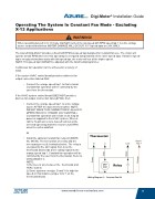
• Install the optional constant fan relay kit (MARS
No. 08595). The kit consists of a relay and the
necessary pre-cut & terminated wires. The relay is
energized by the 24V signal from G on the
thermostat and sends a line voltage signal to the
orange speed tap 1. Constant fan operation will be
controlled by the user from the thermostat. Refer to
wiring diagram C.
NOTE:
1) Remove G wire between the thermostat and
HVAC system.
2) Some systems energize G and Y for high fan
speed; in this instance jumper G to Y on the
thermostat board.
Wiring Diagram C: Constant Fan Kit
www.marsdelivers-contractors.com
9
®