Page 5 - Layout 1
P. 5
Digi-MotorInstallation Guide
®
Configuring The Azure® Digi-Motor
® cont.
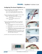
3) Set the motor voltage to match the application using the RED
voltage wire pigtail leads: Refer to image 2.
120V: Connect the RED leads together (closed circuit).
240V: Leave the RED leads disconnected (open circuit).
4) Set the motor rotation to match the application using the WHITE
rotation wire pigtail leads: Refer to image 3.
CWLE: Connect the WHITE rotation leads together
(closed circuit).
CCWLE: Leave the WHITE leads disconnected
(open circuit).
Configuration Leads
5) Set the motor mode of operation (PSC or X-13) to match the
application using the BLUE mode of operation pigtail leads:
Refer to image 4.
PSC: Connect the BLUE mode of operation leads together
(closed circuit).
X-13: Leave the BLUE mode of operation leads disconnected
(open circuit).
Image 2: Voltage
X-13: Install the X-13 PC board into the speed tap wire harness
by unplugging the connector and inserting the X-13 PC
board. Refer to image 5 & 6.
X-13: Unplug and discard the WHITE and GREEN/YELLOW
Azure® power wire harness. (The factory X-13 power
harness will replace this harness)
6) Install the blower assembly back into the HVAC equipment.
Image 3: Rotation
Image 4: Mode of Operation
Image 5: X-13 PC Board
Image 6: X-13 PC Board Location
www.marsdelivers-contractors.com
5
®