Page 6 - Layout 1
P. 6
Digi-MotorInstallation Guide
®
Connecting & Auto Sizing For PSC Applications
NOTICE
This motor must initially be put through a brief programming mode. During this procedure,
the Azure® Digi-Motorwill run for approximately 2 minutes while it measures the external
®
static pressure of the application. This process programs the motor to a horsepower value appropriate for the
application and establishes proper torque values on each of the speed taps. This is necessary for both PSC and
X-13 applications. The auto sizing process can performed as many times as desired. Each auto sizing event
overrides the previous event.
WARNING!
To prevent electric shock, personal injury, or death, turn off the electric power at the disconnect or main service
panel prior to making any electrical connections.
1) Turn off the system thermostat. Make certain all supply registers,
grilles, and zones are open and unobstructed. Make certain the air Ground
Neutral
L2
filter is clean. This is very important for accurate auto sizing and best
performance of Azure®.
Tap 1
Low Tap 2 Tap 3 Tap 4 Tap 5
625 RPM
Med Low
Med
Med High
High
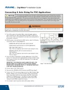
2) With the power removed from the HVAC system, make the following
connections: Refer to wiring diagram A.
Wiring Diagram A: Azure® Harness Connections for
PSC Applications
• GREEN/YELLOW (Ground) lead to system ground
• WHITE (N/L2) lead to Neutral or L2 (230V applications)
• RED (Tap 5 High) lead to L1.
Note: This is a temporary connection for auto sizing the motor.
• BROWN & WHITE (24V & Common) harness to
24V transformer
Note: This is a temporary connection for auto sizing the motor.
Refer to image 7
3) Close the blower housing door. Carefully apply power to the HVAC
system. The motor will run for approximately 2 minutes and then stop.
Note: If power is left on, the motor will restart after 30 seconds and
run at speed tap 5.
IMPORTANT: THE PROCESS IS NOT COMPLETE UNTIL THE
MOTOR COMES TO A COMPLETE STOP. DO NOT REMOVE
Image 7: Auto Size Harness
POWER UNTIL THE MOTOR STOPS. IF THE MOTOR DOES NOT
STOP, SEE TROUBLESHOOTING.
4) Remove power to the HVAC system.
5) Disconnect the BROWN & WHITE harness and RED speed tap 5.
6) Connect the 115V motor speed taps (select from High, Medium High,
Medium, Medium Low, or Low) to the HVAC system control board;
these connections match the connections of the PSC motor being
replaced. See diagram on p.11. Carefully tie off any unused taps.
Note: If low speed (625 RPM) constant fan is desired, proceed to
‘Setting The 625 RPM Constant Fan Feature’.
7) Test complete system operation and confirm proper airflow.
6
www.marsdelivers-contractors.com
®